File Info
| Exam | Implementing Cisco Network Security |
| Number | 210-260 |
| File Name | Cisco.210-260.ExamCollection.2024-12-20.240q.vcex |
| Size | 15 MB |
| Posted | Dec 20, 2024 |
| Download | Cisco.210-260.ExamCollection.2024-12-20.240q.vcex |
How to open VCEX & EXAM Files?
Files with VCEX & EXAM extensions can be opened by ProfExam Simulator.
Coupon: MASTEREXAM
With discount: 20%
Demo Questions
Question 1
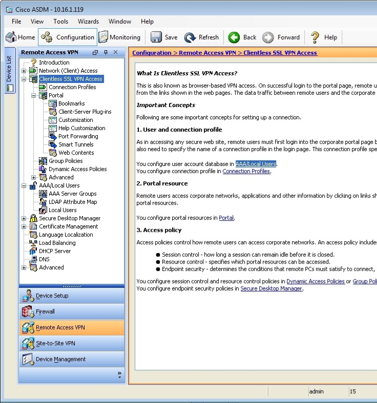
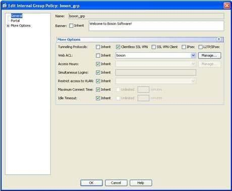
You are using ASDM to verify a clientless SSL VPN configuration made by a junior administrator on an ASA.
Please click exhibit to answer the following questions.
Which of the following tunneling protocols will the jane user account be able to use when establishing a clientless SSL VPN connection by using the boson tunnel group? (Select the best answer.)
Exhibit:

- only clientless SSL VPN
- only SSL VPN client
- only IPSec
- only L2TP/IPSec
- both client and clientless SSL VPN
- both clientless SSL VPN and IPSec
Correct answer: A
Explanation:
The jane user account will be able to use only the clientless Secure Sockets Layer (SSL) virtual private network (VPN) tunneling protocol when establishing a clientless SSL VPN connection by using the boson tunnel group. You can specify the tunneling protocols that can be used to establish a connection to a tunnel group, which is also known as a connection profile, either in a group policy or within a user account, depending on whether the tunneling protocol configuration should be applied to a group or to a single user.When you configure a tunneling protocol, you can specify one or more of the following four options: Clientless SSL VPN, SSL VPN Client, IPSec, or L2TP/IPSec.In this scenario, you can view the tunneling protocols that are configured for the jane user account by accessing her user account information in Cisco Adaptive Security Device Manager (ASDM) by clicking Configuration, clicking the Remote Access VPN button, expanding AAA/Local Users, clicking Local Users, and doubleclicking the jane user account, which will open the Edit User Account dialog box. You should then click VPN Policy, which will display a pane that includes a Tunneling Protocols entry. This entry for the jane user account is configured with the Inherit option, which means that the tunneling protocols that the jane user account can use will be inherited from a group policy that is associated with the jane user account. In this scenario, the jane user account is associated with the boson_grp group policy.To view the tunneling protocols that are associated with the boson_grp group policy in ASDM, you should click Configuration, click the Remote Access VPN button, expand Clientless SSL VPN Access, select Group Policies, and doubleclick boson_grp, which will open the Edit Internal Group Policy dialog box. The More Options section on the General pane displays the Tunneling Protocols entry. Only the Clientless SSL VPNoption is selected, as shown in the following exhibit: Reference:Cisco: General VPN Setup: Adding or Editing a Remote Access Internal Group Policy, General Attributes The jane user account will be able to use only the clientless Secure Sockets Layer (SSL) virtual private network (VPN) tunneling protocol when establishing a clientless SSL VPN connection by using the boson tunnel group. You can specify the tunneling protocols that can be used to establish a connection to a tunnel group, which is also known as a connection profile, either in a group policy or within a user account, depending on whether the tunneling protocol configuration should be applied to a group or to a single user.
When you configure a tunneling protocol, you can specify one or more of the following four options: Clientless SSL VPN, SSL VPN Client, IPSec, or L2TP/IPSec.
In this scenario, you can view the tunneling protocols that are configured for the jane user account by accessing her user account information in Cisco Adaptive Security Device Manager (ASDM) by clicking Configuration, clicking the Remote Access VPN button, expanding AAA/Local Users, clicking Local Users, and doubleclicking the jane user account, which will open the Edit User Account dialog box. You should then click VPN Policy, which will display a pane that includes a Tunneling Protocols entry. This entry for the jane user account is configured with the Inherit option, which means that the tunneling protocols that the jane user account can use will be inherited from a group policy that is associated with the jane user account. In this scenario, the jane user account is associated with the boson_grp group policy.
To view the tunneling protocols that are associated with the boson_grp group policy in ASDM, you should click Configuration, click the Remote Access VPN button, expand Clientless SSL VPN Access, select Group Policies, and doubleclick boson_grp, which will open the Edit Internal Group Policy dialog box. The More Options section on the General pane displays the Tunneling Protocols entry. Only the Clientless SSL VPNoption is selected, as shown in the following exhibit:

Reference:
Cisco: General VPN Setup: Adding or Editing a Remote Access Internal Group Policy, General Attributes
Question 2

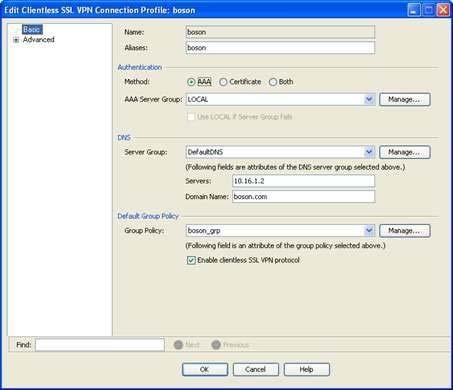

You are using ASDM to verify a clientless SSL VPN configuration made by a junior administrator on an ASA.
Please click exhibit to answer the following questions.
Exhibit:

Which of the following statements are true regarding clientless SSL VPN connections that are made by using the boson tunnel group? (Select 3 choices.)
- VPN clients will be authenticated using the local AAA database.
- VPN clients will be authenticated using digital certificates.
- The DfltGrpPolicy group policy will be applied to the VPN connections.
- The boson_grp group policy will be applied to the VPN connections.
- No welcome banner will be displayed to VPN clients.
- A welcome banner will be displayed to VPN clients.
Correct answer: ADF
Explanation:
Virtual private network (VPN) clients will be authenticated using the local Authentication, Authorization, and Accounting (AAA) database, the boson_grp group policy will be applied to the VPN connections, and a welcome banner will be displayed to VPN clients. When configuring a tunnel group, which is also known as a connection profile, in Cisco Adaptive Security Device Manager (ASDM), you can specify a number of parameters. For example, you can specify the type of authentication to use and the default group policy to use for VPN connections made by using the tunnel group. This information can be configured or modified on the Add or Edit Clientless SSL VPN Connection Profile dialog box in ASDM. To access this dialog box in ASDM, you should click Configuration, click the Remote Access VPN button, expand Clientless SSL VPN Access, and click Connection Profiles. You should then doubleclick a connection profile, which will open the Edit Clientless SSL VPN Connection Profile dialog box for the selected connection profile. The Edit Clientless SSL VPN Connection Profile dialog box for the boson tunnel group is shown in the following exhibit: The Authentication section of the Basic screen of the Edit Clientless SSL VPN Connection Profile dialog box indicates that the tunnel group will use the local AAA database for user authentication. Thus any VPN connections made by using this tunnel group will be authenticated against the AAA database. The Default Group Policy section indicates that the boson_grp group policy will be applied to this connection profile. That is, the settings in the boson_grp group policy will apply to VPN users who connect by using the boson tunnel group. You can view the details of the boson_grp group policy to determine whether a banner message will be displayed to VPN clients. This information is displayed on the Generalpane of the Add or Edit Internal Group Policy dialog box. To view the details of an existing group policy for clientless SSL VPN users in ASDM, you should click Configuration, expand Clientless SSL VPN Access, and click Group Policies. You can then doubleclick boson_grp, which will open the Edit Internal Group Policy dialog box, which is shown in the following exhibit: The Banner entry contains a value of Welcome to Boson Software! Because VPN connections made by using the boson tunnel group will use the boson_grp group policy, you can determine that VPN users will be shown a welcome banner in this scenario.Reference:Cisco: Configuring Tunnel Groups, Group Policies, and Users: Connection ProfilesCisco: General VPN Setup: Adding or Editing a Remote Access Internal Group Policy, General Attributes Virtual private network (VPN) clients will be authenticated using the local Authentication, Authorization, and Accounting (AAA) database, the boson_grp group policy will be applied to the VPN connections, and a welcome banner will be displayed to VPN clients. When configuring a tunnel group, which is also known as a connection profile, in Cisco Adaptive Security Device Manager (ASDM), you can specify a number of parameters. For example, you can specify the type of authentication to use and the default group policy to use for VPN connections made by using the tunnel group. This information can be configured or modified on the Add or Edit Clientless SSL VPN Connection Profile dialog box in ASDM. To access this dialog box in ASDM, you should click Configuration, click the Remote Access VPN button, expand Clientless SSL VPN Access, and click Connection Profiles. You should then doubleclick a connection profile, which will open the Edit Clientless SSL VPN Connection Profile dialog box for the selected connection profile. The Edit Clientless SSL VPN Connection Profile dialog box for the boson tunnel group is shown in the following exhibit:

The Authentication section of the Basic screen of the Edit Clientless SSL VPN Connection Profile dialog box indicates that the tunnel group will use the local AAA database for user authentication. Thus any VPN connections made by using this tunnel group will be authenticated against the AAA database.
The Default Group Policy section indicates that the boson_grp group policy will be applied to this connection profile. That is, the settings in the boson_grp group policy will apply to VPN users who connect by using the boson tunnel group.
You can view the details of the boson_grp group policy to determine whether a banner message will be displayed to VPN clients. This information is displayed on the Generalpane of the Add or Edit Internal Group Policy dialog box. To view the details of an existing group policy for clientless SSL VPN users in ASDM, you should click Configuration, expand Clientless SSL VPN Access, and click Group Policies. You can then doubleclick boson_grp, which will open the Edit Internal Group Policy dialog box, which is shown in the following exhibit:

The Banner entry contains a value of Welcome to Boson Software! Because VPN connections made by using the boson tunnel group will use the boson_grp group policy, you can determine that VPN users will be shown a welcome banner in this scenario.
Reference:
Cisco: Configuring Tunnel Groups, Group Policies, and Users: Connection Profiles
Cisco: General VPN Setup: Adding or Editing a Remote Access Internal Group Policy, General Attributes
Question 3

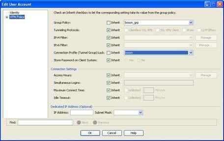
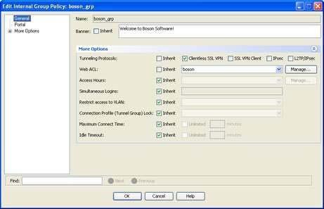
You are using ASDM to verify a clientless SSL VPN configuration made by a junior administrator on an ASA.
Please click exhibit to answer the following questions.
Exhibit:

Which of the following statements is true regarding VPN connections made by a user who is using the john user account? (Select the best answer.)
- The user will be unable to establish a VPN connection by using the boson tunnel group.
- The user will be able to establish a connection by using any tunnel group.
- The DfltGrpPolicy group policy will be applied to any VPN connection that the user established.
- The user will be able to establish only clientless SSL VPN connections.
Correct answer: D
Explanation:
The user will be able to establish only clientless Secure Sockets Layer (SSL) virtual private network (VPN) connections. The tunneling protocols that a user can use to establish a VPN connection can be configured in the user profile or in a group policy. To configure the tunneling protocols in a user profile, you should access the VPN Policy pane of the Add or Edit User Account dialog box. To access this pane, you should click Configuration, click the Remote Access VPN button, expand AAA/Local Users, click Local Users, doubleclick john, and then click VPN Policy. The VPN Policy pane of the john user account is shown in the following exhibit: The Tunneling Protocols entry indicates that the john user account is inheriting the tunneling protocol settings from a group policy. The Group Policy entry indicates that the group policy associated with the john user account is boson_grp. Therefore, you must view the details of the boson_grp group policy to determine the tunneling protocols that the john user account can use.To view the details of the boson_grp group policy, you should click Configuration, expand Clientless SSL VPN Access, click Group Policies, and doubleclick boson_grp, which will open the Edit Internal Group Policy dialog box, as shown in the following exhibit: The Tunneling Protocols entry indicates that the group policy allows only clientless SSL VPN connections.Because the john user account inherits this setting, the john user account will be able to establish a VPN connection by using only a clientless SSL VPN connection.Reference:Cisco: General VPN Setup: Adding or Editing a Remote Access Internal Group Policy, General Attributes The user will be able to establish only clientless Secure Sockets Layer (SSL) virtual private network (VPN) connections. The tunneling protocols that a user can use to establish a VPN connection can be configured in the user profile or in a group policy. To configure the tunneling protocols in a user profile, you should access the VPN Policy pane of the Add or Edit User Account dialog box. To access this pane, you should click Configuration, click the Remote Access VPN button, expand AAA/Local Users, click Local Users, doubleclick john, and then click VPN Policy. The VPN Policy pane of the john user account is shown in the following exhibit:

The Tunneling Protocols entry indicates that the john user account is inheriting the tunneling protocol settings from a group policy. The Group Policy entry indicates that the group policy associated with the john user account is boson_grp. Therefore, you must view the details of the boson_grp group policy to determine the tunneling protocols that the john user account can use.
To view the details of the boson_grp group policy, you should click Configuration, expand Clientless SSL VPN Access, click Group Policies, and doubleclick boson_grp, which will open the Edit Internal Group Policy dialog box, as shown in the following exhibit:

The Tunneling Protocols entry indicates that the group policy allows only clientless SSL VPN connections.
Because the john user account inherits this setting, the john user account will be able to establish a VPN connection by using only a clientless SSL VPN connection.
Reference:
Cisco: General VPN Setup: Adding or Editing a Remote Access Internal Group Policy, General Attributes
Question 4


You are using ASDM to verify a clientless SSL VPN configuration made by a junior administrator on an ASA.
Please click exhibit to answer the following questions.
Exhibit:

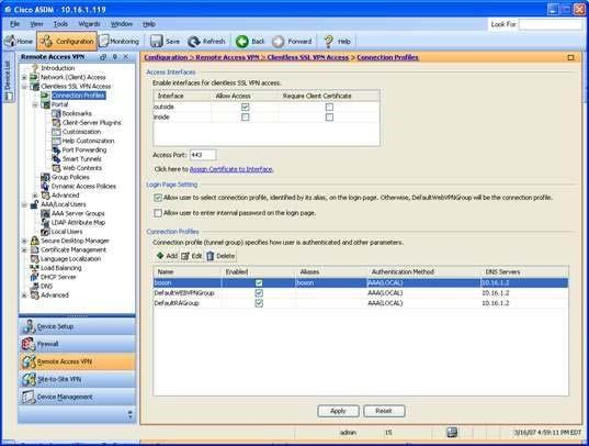
Which of the following connection profiles will use the boson_grp group policy? (Select the best answer.)
- only the boson connection profile
- only the DefaultRAGroup connection profile
- only the DefaultWEBVPNGroup connection profile
- both the boson connection profile and the DefaultWEBVPNGroup connection profile
- both the DefaultRAGroup connection profile and the DefaultWEBVPNGroup
Correct answer: A
Explanation:
Only the boson connection profile will use the boson_grp group policy. To determine which connection profiles will use the boson_grp group policy, you should access the Connection Profiles pane in Cisco Adaptive Security Device Manager (ASDM). To access this pane, you should click Configuration, click the Remote Access VPN button, expand Clientless SSL VPN Access, and click Connection Profiles, which will open the Connection Profiles configuration pane, as shown in the following exhibit: This pane displays a summary of the connection profiles that are configured on the Cisco Adaptive Security Appliance (ASA). In this scenario, there are three connection profiles. There are two default profiles, DefaultRAGroup and DefaultWEBVPNGroup, and one userspecified connection profile, boson. To view which group policy is associated with which connection profile, you should doubleclick the connection profiles to open the Edit Clientless SSL VPN Connection Profile dialog box. The default group policy that is associated with a connection profile is displayed on the Basic pane of this dialog box. By viewing this information, you can determine that only the boson connection profile uses the boson_grp group policy. The Basic pane of the boson connection profile is shown in the following exhibit: The two default connection profiles use the default group policy, which is DfltGrpPolicy.Reference:Cisco: Configuring Tunnel Groups, Group Policies, and Users: Connection Profiles Only the boson connection profile will use the boson_grp group policy. To determine which connection profiles will use the boson_grp group policy, you should access the Connection Profiles pane in Cisco Adaptive Security Device Manager (ASDM). To access this pane, you should click Configuration, click the Remote Access VPN button, expand Clientless SSL VPN Access, and click Connection Profiles, which will open the Connection Profiles configuration pane, as shown in the following exhibit:

This pane displays a summary of the connection profiles that are configured on the Cisco Adaptive Security Appliance (ASA). In this scenario, there are three connection profiles. There are two default profiles, DefaultRAGroup and DefaultWEBVPNGroup, and one userspecified connection profile, boson. To view which group policy is associated with which connection profile, you should doubleclick the connection profiles to open the Edit Clientless SSL VPN Connection Profile dialog box. The default group policy that is associated with a connection profile is displayed on the Basic pane of this dialog box. By viewing this information, you can determine that only the boson connection profile uses the boson_grp group policy. The Basic pane of the boson connection profile is shown in the following exhibit:

The two default connection profiles use the default group policy, which is DfltGrpPolicy.
Reference:
Cisco: Configuring Tunnel Groups, Group Policies, and Users: Connection Profiles
Question 5
Which of the following is typically used to manage a Cisco router in-band? (Select the best answer.)
- a VTY port
- a serial port
- a console port
- an auxiliary port
Correct answer: A
Explanation:
A virtual terminal (VTY) port is typically used to manage a Cisco router in-band. When a Cisco device is operating in its normal state, another device can connect to it by using VTY application protocols such as Telnet or Secure Shell (SSH). The use of VTY lines typically allows multiple administrators or management applications to concurrently access a device from more than one location.You would not use a console port or an auxiliary (AUX) port to manage a Cisco router in-band. You are most likely to use either an AUX port or a console port to manage a Cisco router out-of-band, such as when the router is in read-only memory (ROM) monitor (ROMmon) mode. The AUX port on a Cisco router is typically capable of supporting most of the features available on a console port. Cisco switches either do not have AUX ports or do not support certain features, such as system recovery, on their AUX ports if they have them. ROMmon is a management mode that Cisco routers and switches revert to when the system cannot find a software image, the software image is corrupted, or the configuration register has been set to manually enter ROMmon mode. Because ROMmon is an out-of-band management method, it can be used to recover system software images, passwords, or other configuration data even when the router or switch is in a state where it can no longer forward packets. You would not use a serial port to manage a Cisco router in-band. Serial ports and Ethernet ports are used to directly connect Cisco routers to other network devices. For example, you might use a serial port to directly connect a Cisco router to other data terminal equipment (DTE) or data circuit-terminating equipment (DCE) devices. You would also use a serial port to connect a router to a Channel Service Unit/Data Service Unit (CSU/DSU).Reference:Cisco: Cisco Guide to Harden Cisco IOS Devices: Management Interface Use A virtual terminal (VTY) port is typically used to manage a Cisco router in-band. When a Cisco device is operating in its normal state, another device can connect to it by using VTY application protocols such as Telnet or Secure Shell (SSH). The use of VTY lines typically allows multiple administrators or management applications to concurrently access a device from more than one location.
You would not use a console port or an auxiliary (AUX) port to manage a Cisco router in-band. You are most likely to use either an AUX port or a console port to manage a Cisco router out-of-band, such as when the router is in read-only memory (ROM) monitor (ROMmon) mode. The AUX port on a Cisco router is typically capable of supporting most of the features available on a console port. Cisco switches either do not have AUX ports or do not support certain features, such as system recovery, on their AUX ports if they have them.
ROMmon is a management mode that Cisco routers and switches revert to when the system cannot find a software image, the software image is corrupted, or the configuration register has been set to manually enter ROMmon mode. Because ROMmon is an out-of-band management method, it can be used to recover system software images, passwords, or other configuration data even when the router or switch is in a state where it can no longer forward packets.
You would not use a serial port to manage a Cisco router in-band. Serial ports and Ethernet ports are used to directly connect Cisco routers to other network devices. For example, you might use a serial port to directly connect a Cisco router to other data terminal equipment (DTE) or data circuit-terminating equipment (DCE) devices. You would also use a serial port to connect a router to a Channel Service Unit/Data Service Unit (CSU/DSU).
Reference:
Cisco: Cisco Guide to Harden Cisco IOS Devices: Management Interface Use
Question 6

Which of the following enables the validation of both user and device credentials in a single EAP transaction?
(Select the best answer.)
- PEAP
- EAP-FAST
- EAP-FAST with EAP chaining
- EAP-MD5
Correct answer: C
Explanation:
Extensible Authentication Protocol (EAP)Flexible Authentication via Secure Tunneling (FAST) with EAP chaining, which is also sometimes called EAPFAST version 2 (EAPFASTv2), enables the validation of both user and device credentials in a single EAP transaction. EAP chaining enables a Cisco security device to validate authentication credentials for both a user and the user’s device. In order to enable EAP chaining, both the Cisco security device and the supplicant device must support EAP chaining. The Cisco security device will assign a different level of authorization access depending on one of four success and failure possibilities, as shown in the following table: EAPFAST is an authentication protocol that can be used for point-to-point connections and for both wired and wireless links. The EAPFAST authentication process consists of three phases. The first phase, which is optional and is considered phase 0, consists of provisioning a client with a PAC, which is a digital credential that is used for authentication. A PAC can be manually configured on a client, in which case phase 0 is not required. The second phase, which is referred to as phase 1, involves creating a secure tunnel between the client and the server. The final phase, which is referred to as phase 2, involves authenticating the client. If the client is authenticated, the client will be able to access the network.EAPTransport Layer Security (TLS) is an Internet Engineering Task Force (IETF) standard that is defined in Request for Comments (RFC) 5216. It does not support EAP chaining. Protected EAP (PEAP) is an open standard developed by Cisco, Microsoft, and RSA? it does not support EAP chaining. EAPMessage Digest 5 (MD5) uses an MD5 hash function to provide security and is therefore considered weak when compared to later methods. EAP is an IETF standard that was originally defined in RFC 2284? it does not support EAP chaining.Reference:Cisco: Cisco Identity Services Engine Administrator Guide, Release 1.3: Allowed Protocols Extensible Authentication Protocol (EAP)Flexible Authentication via Secure Tunneling (FAST) with EAP chaining, which is also sometimes called EAPFAST version 2 (EAPFASTv2), enables the validation of both user and device credentials in a single EAP transaction. EAP chaining enables a Cisco security device to validate authentication credentials for both a user and the user’s device. In order to enable EAP chaining, both the Cisco security device and the supplicant device must support EAP chaining. The Cisco security device will assign a different level of authorization access depending on one of four success and failure possibilities, as shown in the following table:

EAPFAST is an authentication protocol that can be used for point-to-point connections and for both wired and wireless links. The EAPFAST authentication process consists of three phases. The first phase, which is optional and is considered phase 0, consists of provisioning a client with a PAC, which is a digital credential that is used for authentication. A PAC can be manually configured on a client, in which case phase 0 is not required. The second phase, which is referred to as phase 1, involves creating a secure tunnel between the client and the server. The final phase, which is referred to as phase 2, involves authenticating the client. If the client is authenticated, the client will be able to access the network.
EAPTransport Layer Security (TLS) is an Internet Engineering Task Force (IETF) standard that is defined in Request for Comments (RFC) 5216. It does not support EAP chaining. Protected EAP (PEAP) is an open standard developed by Cisco, Microsoft, and RSA? it does not support EAP chaining.
EAPMessage Digest 5 (MD5) uses an MD5 hash function to provide security and is therefore considered weak when compared to later methods. EAP is an IETF standard that was originally defined in RFC 2284? it does not support EAP chaining.
Reference:
Cisco: Cisco Identity Services Engine Administrator Guide, Release 1.3: Allowed Protocols
Question 7
Which of the following features protects the control plane by classifying traffic into three separate control plane subinterfaces? (Select the best answer.)
- CoPP
- CPPr
- RBAC
- uRPF
Correct answer: B
Explanation:
Control Plane Protection (CPPr) protects the control plane by classifying control plane traffic into three separate subinterfaces: the host subinterface, the transit subinterface, and the Cisco Express Forwarding (CEF)exception subinterface. The host subinterface contains control plane IP traffic that is destined for a router interface, including traffic from the following sources and protocols:Terminating tunnelsSecure Shell (SSH)Simple Network Management Protocol (SNMP)Internal Border Gateway Protocol (iBGP)Enhanced Interior Gateway Routing Protocol (EIGRP)The transit subinterface contains control plane IP traffic that is traversing the router, including the following traffic:Nonterminating tunnel trafficTraffic that is softwareswitched by the route processorThe CEFexception subinterface contains control plane traffic that is redirected by CEF for process switching, as well as traffic from the following sources and protocols:NonIP hostsAddress Resolution Protocol (ARP) External BGP (eBGP)Open Shortest Path First (OSPF)Label Distribution Protocol (LDP)Layer 2 keepalivesCPPr is used to protect the control plane by filtering and rate limiting traffic in order to prevent excessive CPU and memory consumption. To configure CPPr, you must perform the following steps:Create access control lists (ACLs) to identify traffic.Create a traffic class.Create a traffic policy, and associate the traffic class to the policy- Apply the policy to the specific control plane subinterface.Control Plane Policing (CoPP) is similar to CPPr, except CoPP does not separate control plane traffic into three subinterfaces. To configure CoPP, you must perform the following steps:Create ACLs to identify traffic.Create a traffic class.Create a traffic policy, and associate the traffic class to the policy.Apply the policy to the control plane interface.Both CoPP and CPPr use class maps to filter and ratelimit traffic. However, CPPr separates control plane traffic into three subinterfaces: the host subinterface, the transit subinterface, and the Cisco Express Forwarding (CEF)exception subinterface. For this reason, Cisco recommends that you use CPPr instead of CoPP whenever possible.RoleBased Access Control (RBAC) does not protect the control plane. RBAC protects the management plane by granting limited access to administrators so that they can perform only the tasks required for their job. For example, you can configure permissions on an administrator's account so that the administrator can issue only certain commands, which will prevent the administrator from making unauthorized configuration changes or from viewing restricted information. Unicast Reverse Path Forwarding (uRPF) does not protect the control plane. uRPF protects the data plane by checking the source IP address of a packet to determine whether an inbound packet arrived on the best path back to the source based on routing table information. If the uRPF check passes, the packet is transmitted? if the uRPF check fails, the packet is dropped.Reference:Cisco: Control Plane Protection Control Plane Protection (CPPr) protects the control plane by classifying control plane traffic into three separate subinterfaces: the host subinterface, the transit subinterface, and the Cisco Express Forwarding (CEF)exception subinterface. The host subinterface contains control plane IP traffic that is destined for a router interface, including traffic from the following sources and protocols:
- Terminating tunnels
- Secure Shell (SSH)
- Simple Network Management Protocol (SNMP)
- Internal Border Gateway Protocol (iBGP)
- Enhanced Interior Gateway Routing Protocol (EIGRP)
The transit subinterface contains control plane IP traffic that is traversing the router, including the following traffic:
- Nonterminating tunnel traffic
- Traffic that is softwareswitched by the route processor
The CEFexception subinterface contains control plane traffic that is redirected by CEF for process switching, as well as traffic from the following sources and protocols:
- NonIP hosts
- Address Resolution Protocol (ARP)
- External BGP (eBGP)
- Open Shortest Path First (OSPF)
- Label Distribution Protocol (LDP)
- Layer 2 keepalives
CPPr is used to protect the control plane by filtering and rate limiting traffic in order to prevent excessive CPU and memory consumption. To configure CPPr, you must perform the following steps:
- Create access control lists (ACLs) to identify traffic.
- Create a traffic class.
- Create a traffic policy, and associate the traffic class to the policy
- Apply the policy to the specific control plane subinterface.
Control Plane Policing (CoPP) is similar to CPPr, except CoPP does not separate control plane traffic into three subinterfaces. To configure CoPP, you must perform the following steps:
- Create ACLs to identify traffic.
- Create a traffic class.
- Create a traffic policy, and associate the traffic class to the policy.
- Apply the policy to the control plane interface.
Both CoPP and CPPr use class maps to filter and ratelimit traffic. However, CPPr separates control plane traffic into three subinterfaces: the host subinterface, the transit subinterface, and the Cisco Express Forwarding (CEF)exception subinterface. For this reason, Cisco recommends that you use CPPr instead of CoPP whenever possible.
RoleBased Access Control (RBAC) does not protect the control plane. RBAC protects the management plane by granting limited access to administrators so that they can perform only the tasks required for their job. For example, you can configure permissions on an administrator's account so that the administrator can issue only certain commands, which will prevent the administrator from making unauthorized configuration changes or from viewing restricted information.
Unicast Reverse Path Forwarding (uRPF) does not protect the control plane. uRPF protects the data plane by checking the source IP address of a packet to determine whether an inbound packet arrived on the best path back to the source based on routing table information. If the uRPF check passes, the packet is transmitted? if the uRPF check fails, the packet is dropped.
Reference:
Cisco: Control Plane Protection
Question 8
Which of the following is an outputspreading technique that spammers use to manipulate reputation scores and defeat filters? (Select the best answer.)
- phishing
- snowshoe spam
- waterfalling
- listwashing
Correct answer: B
Explanation:
Of the available choices, snowshoe spam is an outputspreading technique that spammers use to manipulate reputation scores and defeat filters. Snowshoe spammers establish many false company names and identities, often with unique post office addresses and telephone numbers, so that reputation filters do not perceive the source of the spam as a threat. In addition, the spam output is spread across multiple IP addresses and domain names in order to defeat blacklists. The Cisco Context Adaptive Scanning Engine (CASE) on a Cisco Email Security Appliance (ESA) is a contextual analysis technology that is intended to detect email threats, such as snowshoe spam, as they are received. CASE checks the reputation of email senders, scans the content of email messages, and analyzes the construction of email messages. As part of this process, CASE submits the email sender to the Cisco SenderBase Network, which contains data on hundreds of thousands of email networks. The sender is assigned a score based on this information. The content of the email messaging is scanned because it could contain language, links, or a call to action that is indicative of a phishing scam.Phishing is a social engineering technique in which a malicious person uses a seemingly legitimate electronic communication, such as email or a webpage, in an attempt to dupe a user into submitting personal information, such as a Social Security number (SSN), account login information, or financial information. To mitigate the effects of a phishing attack, users should use email clients and web browsers that provide phishing filters. In addition, users should also be wary of any unsolicited email or web content that requests personal information. The CASE on a Cisco ESA appliance is capable of detecting phishing scams.Listwashing is a spammer technique of cleaning lists of email recipients who complain about spam but without stopping the spam from being sent to other recipients who do not complain. Listwashing is similar to an optout address policy, meaning that email addresses are included in the list without the permission of the email address owner and only removed if the owner complains. Waterfalling is a spammer technique of cleaning lists of email recipients by sending the lists through multiple email service providers. Spammers with bad lists use this technique to uncover email addresses that bounce or that result in complaints against the spammer. The spammer can then remove those email addresses from the list, which increases the likelihood that spam will be delivered to the remaining recipients.Reference:Cisco: Cisco Email Security Appliance Data SheetSpamhaus: Frequently Asked Questions (FAQ): Snowshoe Spamming Of the available choices, snowshoe spam is an outputspreading technique that spammers use to manipulate reputation scores and defeat filters. Snowshoe spammers establish many false company names and identities, often with unique post office addresses and telephone numbers, so that reputation filters do not perceive the source of the spam as a threat. In addition, the spam output is spread across multiple IP addresses and domain names in order to defeat blacklists.
The Cisco Context Adaptive Scanning Engine (CASE) on a Cisco Email Security Appliance (ESA) is a contextual analysis technology that is intended to detect email threats, such as snowshoe spam, as they are received. CASE checks the reputation of email senders, scans the content of email messages, and analyzes the construction of email messages. As part of this process, CASE submits the email sender to the Cisco SenderBase Network, which contains data on hundreds of thousands of email networks. The sender is assigned a score based on this information. The content of the email messaging is scanned because it could contain language, links, or a call to action that is indicative of a phishing scam.
Phishing is a social engineering technique in which a malicious person uses a seemingly legitimate electronic communication, such as email or a webpage, in an attempt to dupe a user into submitting personal information, such as a Social Security number (SSN), account login information, or financial information. To mitigate the effects of a phishing attack, users should use email clients and web browsers that provide phishing filters. In addition, users should also be wary of any unsolicited email or web content that requests personal information. The CASE on a Cisco ESA appliance is capable of detecting phishing scams.
Listwashing is a spammer technique of cleaning lists of email recipients who complain about spam but without stopping the spam from being sent to other recipients who do not complain. Listwashing is similar to an optout address policy, meaning that email addresses are included in the list without the permission of the email address owner and only removed if the owner complains.
Waterfalling is a spammer technique of cleaning lists of email recipients by sending the lists through multiple email service providers. Spammers with bad lists use this technique to uncover email addresses that bounce or that result in complaints against the spammer. The spammer can then remove those email addresses from the list, which increases the likelihood that spam will be delivered to the remaining recipients.
Reference:
Cisco: Cisco Email Security Appliance Data Sheet
Spamhaus: Frequently Asked Questions (FAQ): Snowshoe Spamming
Question 9
You are configuring dynamic PAT on a Cisco ASA 5500 using the CLI. The ASA is running software version 8.3.
Which of the following IP addresses can you configure inline? (Select the best answer.)
- inside global
- outside global
- inside local
- outside local
Correct answer: A
Explanation:
You can configure an inside global address inline if you are configuring dynamic Port Address Translation (PAT) on a Cisco Adaptive Security Appliance (ASA) using the commandline interface (CLI). A global address is a source or destination IP address as seen from the perspective of a host on the outside network. An inside global address is an IP address that represents an internal host to the outside network? it can be configured inline by using the nat command or defined within a network object.On a Cisco ASA, a network object is a data structure that is used in place of inline IP information. You might use a network object in place of configuring IP addresses, subnet masks, protocols, and port numbers if you must configure that same information in multiple places. If the information you configure within the object ever changes, you then need only modify the single object instead of locating and modifying each instance of the inline IP information.An object group is simply a group of network objects. By grouping network objects, you can enable the use of a single application control engine (ACE) to make requests of multiple devices.Inside global addresses are typically public IP addresses assigned by the administrator of the outside network.Dynamic PAT can translate many inside local IP addresses to a single inside global IP address. In ASA terms, the inside global address is also known as the mapped address, because it is the IP address that you want to map to.You are more likely to configure an inside local address in a network object or object group, not inline. A local address is a source or destination IP address as seen from the perspective of a host on the inside network. An inside local address is an IP address that represents an internal host to the inside network. Inside local addresses are typically private IP addresses defined by Request for Comments (RFC) 1918. When a NAT router receives a packet from a local host destined for the Internet, the router changes the inside local address to an inside global address and forwards the packet to its destination. You would not necessarily configure an outside local address in this scenario. An outside local address is an IP address that represents an external host to the inside network. The outside local address is often the same as the outside global address, particularly when inside hosts attempt to access resources on the Internet.However, in some configurations, it is necessary to configure a NAT translation that allows a local address on the internal network to identify an outside host. You would not configure an outside global address in this scenario. An outside global address is an IP address that represents an external host to the outside network. Outside global addresses are typically public IP addresses assigned to an Internet host by the host’s operator. The outside global address is usually the address registered with the Domain Name System (DNS) server that maps a host’s public IP address to a friendly name, such as .Reference:Cisco: Cisco ASA 5500 Series Configuration Guide Using the CLI, 8.3: Configuring Dynamic PAT (Hide) You can configure an inside global address inline if you are configuring dynamic Port Address Translation (PAT) on a Cisco Adaptive Security Appliance (ASA) using the commandline interface (CLI). A global address is a source or destination IP address as seen from the perspective of a host on the outside network. An inside global address is an IP address that represents an internal host to the outside network? it can be configured inline by using the nat command or defined within a network object.
On a Cisco ASA, a network object is a data structure that is used in place of inline IP information. You might use a network object in place of configuring IP addresses, subnet masks, protocols, and port numbers if you must configure that same information in multiple places. If the information you configure within the object ever changes, you then need only modify the single object instead of locating and modifying each instance of the inline IP information.
An object group is simply a group of network objects. By grouping network objects, you can enable the use of a single application control engine (ACE) to make requests of multiple devices.
Inside global addresses are typically public IP addresses assigned by the administrator of the outside network.
Dynamic PAT can translate many inside local IP addresses to a single inside global IP address. In ASA terms, the inside global address is also known as the mapped address, because it is the IP address that you want to map to.
You are more likely to configure an inside local address in a network object or object group, not inline. A local address is a source or destination IP address as seen from the perspective of a host on the inside network. An inside local address is an IP address that represents an internal host to the inside network. Inside local addresses are typically private IP addresses defined by Request for Comments (RFC) 1918. When a NAT router receives a packet from a local host destined for the Internet, the router changes the inside local address to an inside global address and forwards the packet to its destination.
You would not necessarily configure an outside local address in this scenario. An outside local address is an IP address that represents an external host to the inside network. The outside local address is often the same as the outside global address, particularly when inside hosts attempt to access resources on the Internet.
However, in some configurations, it is necessary to configure a NAT translation that allows a local address on the internal network to identify an outside host.
You would not configure an outside global address in this scenario. An outside global address is an IP address that represents an external host to the outside network. Outside global addresses are typically public IP addresses assigned to an Internet host by the host’s operator. The outside global address is usually the address registered with the Domain Name System (DNS) server that maps a host’s public IP address to a friendly name, such as .
Reference:
Cisco: Cisco ASA 5500 Series Configuration Guide Using the CLI, 8.3: Configuring Dynamic PAT (Hide)
Question 10
Your company’s active ASA currently shares its stateful failover link with a regular data interface. Your supervisor asks you to configure a failover key on both the active ASA and the standby ASA.
Which of the following is most likely the reason? (Select the best answer.)
- so that the risk of exposure of VPN configuration information is mitigated
- so that both ASA devices forward traffic for a given group of security contexts
- so that the active ASA can monitor the status of the standby ASA
- so that the stateful failover link cannot use a regular data interface
Correct answer: A
Explanation:
Most likely, you would configure a failover key on both the active Cisco Adaptive Security Appliance (ASA) and the standby ASA so that the risk of exposure of virtual private network (VPN) configuration is mitigated. An ASA can share its stateful failover link with a regular data interface only when the unit is operating in single context, routed mode. However, Cisco strongly recommends using a dedicated Ethernet interface or sharing a LAN failover link instead because stateful failover traffic can increase the possibility of congestion and can negatively impact the performance of the shared data interface. In addition, all LAN failover and stateful failover information is transmitted as clear text by default. Therefore, sharing the stateful failover link with a regular data interface can unnecessarily expose VPN configuration information, such as user names, passwords, and preshared keys (PSKs) to malicious users on the shared network segment. You can mitigate this risk by configuring a failover key on both the active unit and the standby unit to protect failover information.You would not configure a failover key so that the active ASA can monitor the status of the standby ASA. An ASA can be configured to participate in either an active/standby or an active/active failover configuration. In an active/standby configuration, one ASA serves as the active unit and forwards traffic. A second ASA functions as a standby unit, which monitors the status of the active unit. If a failover event is triggered, the standby unit takes on the role of the active unit.You would not configure a failover key so that both ASA devices forward traffic for a given group of security contexts. An active/active failover configuration enables both ASAs to forward traffic for a select group of security contexts. With active/active failover, two failover groups exist as security contexts on each ASA. When a failover event is triggered, a failover group can become active on a standby unit or the entire standby unit can become the new active unit. Because an active/active failover configuration relies on security contexts, both ASAs must be in multiple context mode before active/active failover can be implemented. The failoverconfiguration for each unit in an active/active failover configuration is managed from within the system context.Unlike user contexts, the system context does not contain any normal data interfaces.You would not configure a failover key so that the stateful failover link cannot use a regular data interface.Instead, you would configure an ASA to operate in multiple context, routed mode or multiple context, transparent mode. An ASA operating in multiple context, routed mode or multiple context, transparent mode does not support using a regular data interface as the stateful failover link. When an ASA is operating in multiple context mode, the stateful failover link resides in the system context, which does not contain any regular data interfaces. Thus the stateful failover link cannot be a shared data link.The implementation of the failover process between the active and standby units can be either stateless or stateful. In a stateless failover implementation, the standby unit of a failover pair takes on the IP and Media Access Control (MAC) addresses of the old active unit during a failover event. This mechanism enablesnetwork clients to maintain their existing network configurations? however, because no network state information is retained, the clients must reestablish their network connections through the new active unit. By contrast, the active unit in a stateful failover implementation transmits certain types of state information through a stateful failover link to the standby unit. This exchange of state information ensures that the standby unit can preserve the state information for open connections during the failover process. Because the state information is preserved, the impact of a failover event on network hosts with open connections can be mitigated.Reference:Cisco: Information About High Availability: Stateful Failover Link Most likely, you would configure a failover key on both the active Cisco Adaptive Security Appliance (ASA) and the standby ASA so that the risk of exposure of virtual private network (VPN) configuration is mitigated. An ASA can share its stateful failover link with a regular data interface only when the unit is operating in single context, routed mode. However, Cisco strongly recommends using a dedicated Ethernet interface or sharing a LAN failover link instead because stateful failover traffic can increase the possibility of congestion and can negatively impact the performance of the shared data interface. In addition, all LAN failover and stateful failover information is transmitted as clear text by default. Therefore, sharing the stateful failover link with a regular data interface can unnecessarily expose VPN configuration information, such as user names, passwords, and preshared keys (PSKs) to malicious users on the shared network segment. You can mitigate this risk by configuring a failover key on both the active unit and the standby unit to protect failover information.
You would not configure a failover key so that the active ASA can monitor the status of the standby ASA. An ASA can be configured to participate in either an active/standby or an active/active failover configuration. In an active/standby configuration, one ASA serves as the active unit and forwards traffic. A second ASA functions as a standby unit, which monitors the status of the active unit. If a failover event is triggered, the standby unit takes on the role of the active unit.
You would not configure a failover key so that both ASA devices forward traffic for a given group of security contexts. An active/active failover configuration enables both ASAs to forward traffic for a select group of security contexts. With active/active failover, two failover groups exist as security contexts on each ASA. When a failover event is triggered, a failover group can become active on a standby unit or the entire standby unit can become the new active unit. Because an active/active failover configuration relies on security contexts, both ASAs must be in multiple context mode before active/active failover can be implemented. The failoverconfiguration for each unit in an active/active failover configuration is managed from within the system context.
Unlike user contexts, the system context does not contain any normal data interfaces.
You would not configure a failover key so that the stateful failover link cannot use a regular data interface.
Instead, you would configure an ASA to operate in multiple context, routed mode or multiple context, transparent mode. An ASA operating in multiple context, routed mode or multiple context, transparent mode does not support using a regular data interface as the stateful failover link. When an ASA is operating in multiple context mode, the stateful failover link resides in the system context, which does not contain any regular data interfaces. Thus the stateful failover link cannot be a shared data link.
The implementation of the failover process between the active and standby units can be either stateless or stateful. In a stateless failover implementation, the standby unit of a failover pair takes on the IP and Media Access Control (MAC) addresses of the old active unit during a failover event. This mechanism enablesnetwork clients to maintain their existing network configurations? however, because no network state information is retained, the clients must reestablish their network connections through the new active unit. By contrast, the active unit in a stateful failover implementation transmits certain types of state information through a stateful failover link to the standby unit. This exchange of state information ensures that the standby unit can preserve the state information for open connections during the failover process. Because the state information is preserved, the impact of a failover event on network hosts with open connections can be mitigated.
Reference:
Cisco: Information About High Availability: Stateful Failover Link

